2023


Hydraulic tilt flume - Federal Agency of Water Management - Institute of Hydraulic Engineering and Hydrometry, BOKU Hydraulic Engineering Laboratory Vienna, Austria

Design, manufacture and installation of a hydraulic measuring flume with 3D measuring carriage.

Total length of the system 21,50 m
Total width of the system 2,50 m
Total height of the system 2,40 m
Effective length of the flume 17,90 m
Effective width of the flume 0,60 m
Effective height of the flume walls 0,49 m
Maximum slope of the flume 5,0 %
Maximum flow rate 250 l/s

2023


Hydrotechnical laboratory - Department of Landscape Engineering, Faculty of Horticulture and Landscape Engineering, Slovak University of Agriculture in Nitra, Slovakia

Design, manufacture and installation of the mechanical and electrical parts of the hydrotechnical laboratory. The delivery included a hydraulic circuit, two hydraulic flumes with models of water structures, measurement, control and visualization of non-electrical parameters.

Total laboratory area 290 m2
Total flow capacity of the laboratory 100 l/s
Hydraulic flume Ž1 - length/depth/width 8,1/0,40/0,40 m
Hydraulic flume Ž2 - length/depth/width 10,0/0,40/0,40 m
Hydraulic flume Ž2 - slope -1 % až 6,4 %

2022


Renovation of the hydraulic measuring flume of the laboratory of the Institute of Water Structures, Faculty of Civil Engineering VUT Brno

Renovation and upgrade of the hydraulic measuring flume in the laboratory of the Institute of Water Structures of the Faculty of Civil Engineering VUT Brno. The nominal width of the chute remained at 0.40 m. The effective height of the glasses was increased by 0.10 m to a total of 0.50 m. The flow capacity of the chute was increased from 40 l/s to 60 l/s.

Total flume length 15,5 m
Effective flume length 12,0 m
Effective flume width 0,409 m
Effective flume wall height 0,49 m
Min. flow capacity 0,2 l/s
Max. flow capacity 60 l/s

2021


Hydraulic circuit with a measuring flume - Teaching laboratory MENDELU Faculty of AgriSciences

The hydraulic circuit with measuring flume is located in the first underground floor of building Q of the Faculty of AgriSciences. It is a recirculating hydraulic circuit with above-ground storage tanks, from which the water reaches the space of the measuring flume with the help of a pump through a discharge pipe. It is also possible to use the so-called reserve before the inflow into the measuring flume, which enables any models in the room to be supplied with water. Control of the direction of water flow in the hydraulic circuit is ensured by the manually controlled shut-off valves. Four interconnected polypropylene storage tanks have a total volume of 3.9 m3. The supply pipe of a centrifugal pump with an input of 2.4 kW is connected to one of the storage tanks. The pump is dimensioned in such a way that it is able to ensure a continuos water flow of up to 40 l/s in the measuring flume through a DN 100 stainless steel pipe connection. A magnetic-induction flowmeter DN 100 is used to measure the flow rate, which ensures minimum measurable flow rates from 1.6 l/s. The main measuring part of the hydraulic circuit consists of a measuring flume with a total length of 6.50 m. It is designed as solid, non-tilting with glass side walls, a stainless steel bottom and an effective width of 0.370 m. The glass walls consist of individual 10 mm thick glass panes bonded to the supporting structure with a specialized sealant. The electro-technological part of the laboratory consists of a switchboard with simple pump speed control using a potentiometer-controlled variable-frequency drive .

Total flume length 6,5 m
Effective flume length 5,0 m
Effective flume width 0,37 m
Effective flume wall height 0,39 m
Min. flow capacity 1,6 l/s
Max. flow capacity 40 l/s
Storage tank capacity 3,9 m3

2016


Hydraulic Measuring Flume for the Brno University of Technology/NIVUS GmbH

Production of a special measuring flume for the measurement needs of NIVUS GmbH on the premises of the Brno University of Technology, Faculty of Civil Engineering. The measuring flume made of steel galvanized construction has the following parameters:

Total flume length 6,3 m
Effective flume length 5,0 m
Effective flume width 0,5 m
Effective flume wall height 2,2 m (rezerva – 0,05 m)
Total height of measuring flume structure 2,6 m

2014


Hydraulic Laboratory of the School of Civil Engineering in Vysoké Mýto

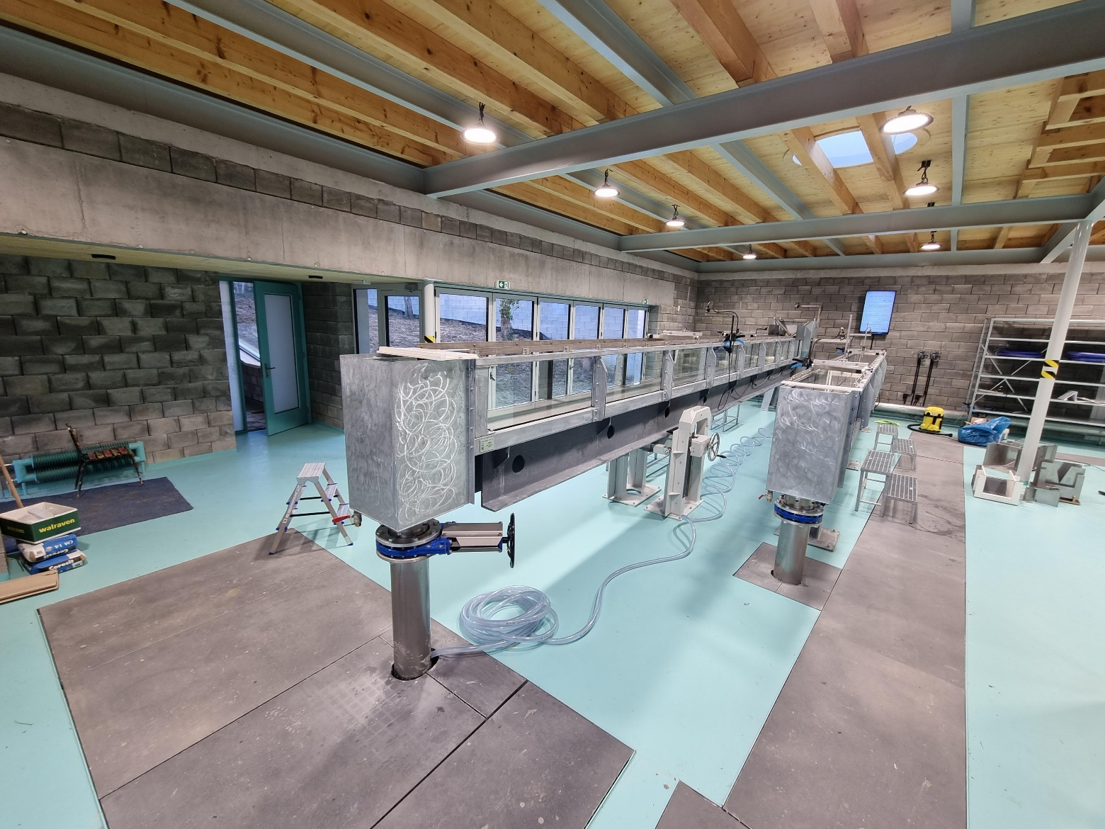
The hydraulic circuit of the laboratory consists of three basic elements – s storage tank, distribution pipes and connected measuring tracks. 
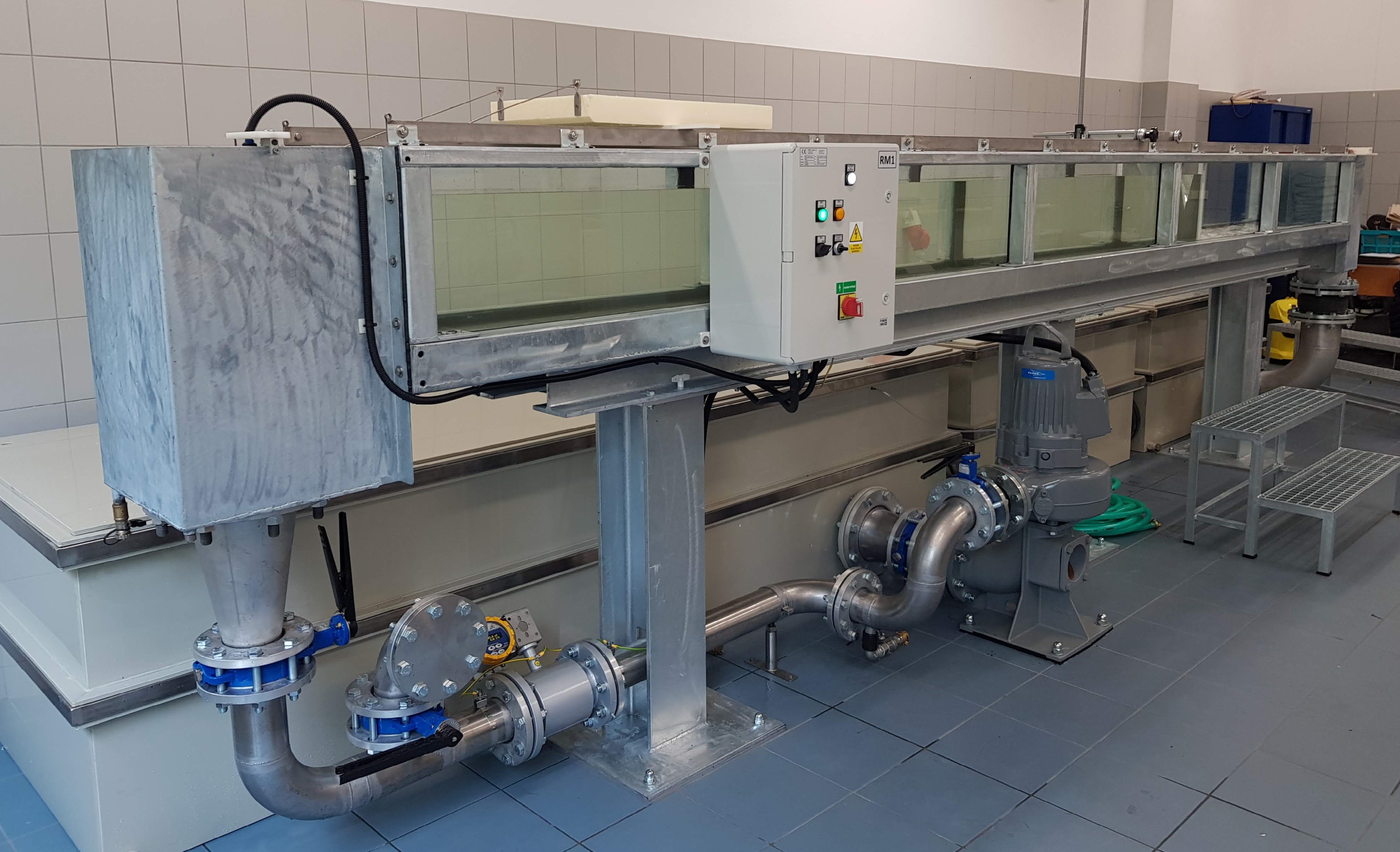
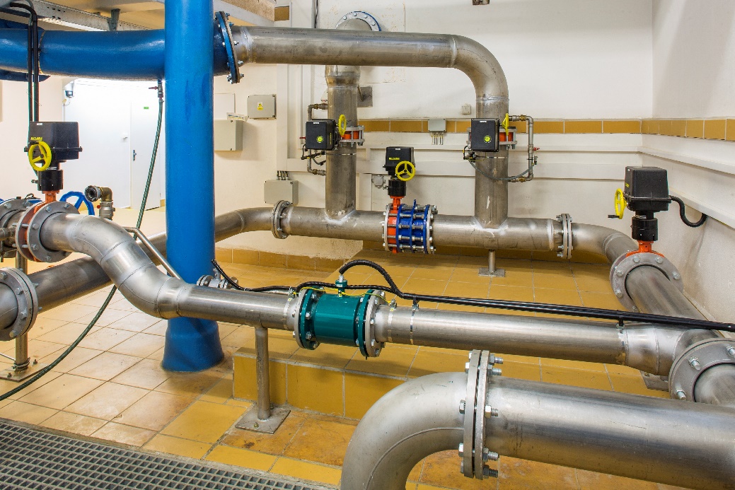
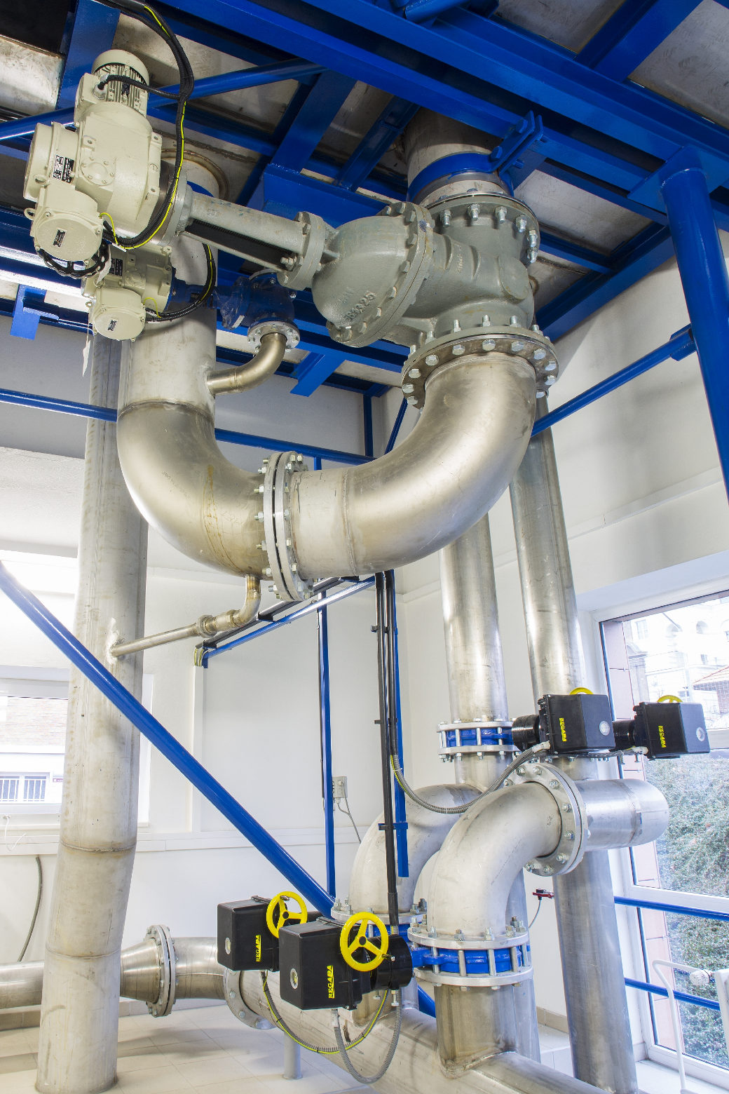
The underground storage tank, which also makes up a pumping and storage reservoir, is of rectangular ground plan with a total capacity of 6.5 m3. In the tank, there are two submersible centrifugal pumps with a total power input of 4 kW and a maximum capacity of 36 l/s. The water is transported from the pumps by a stainless steel pipeline to two pressure branches of the hydraulic circuit in dimensions DN 100 and DN 50. 
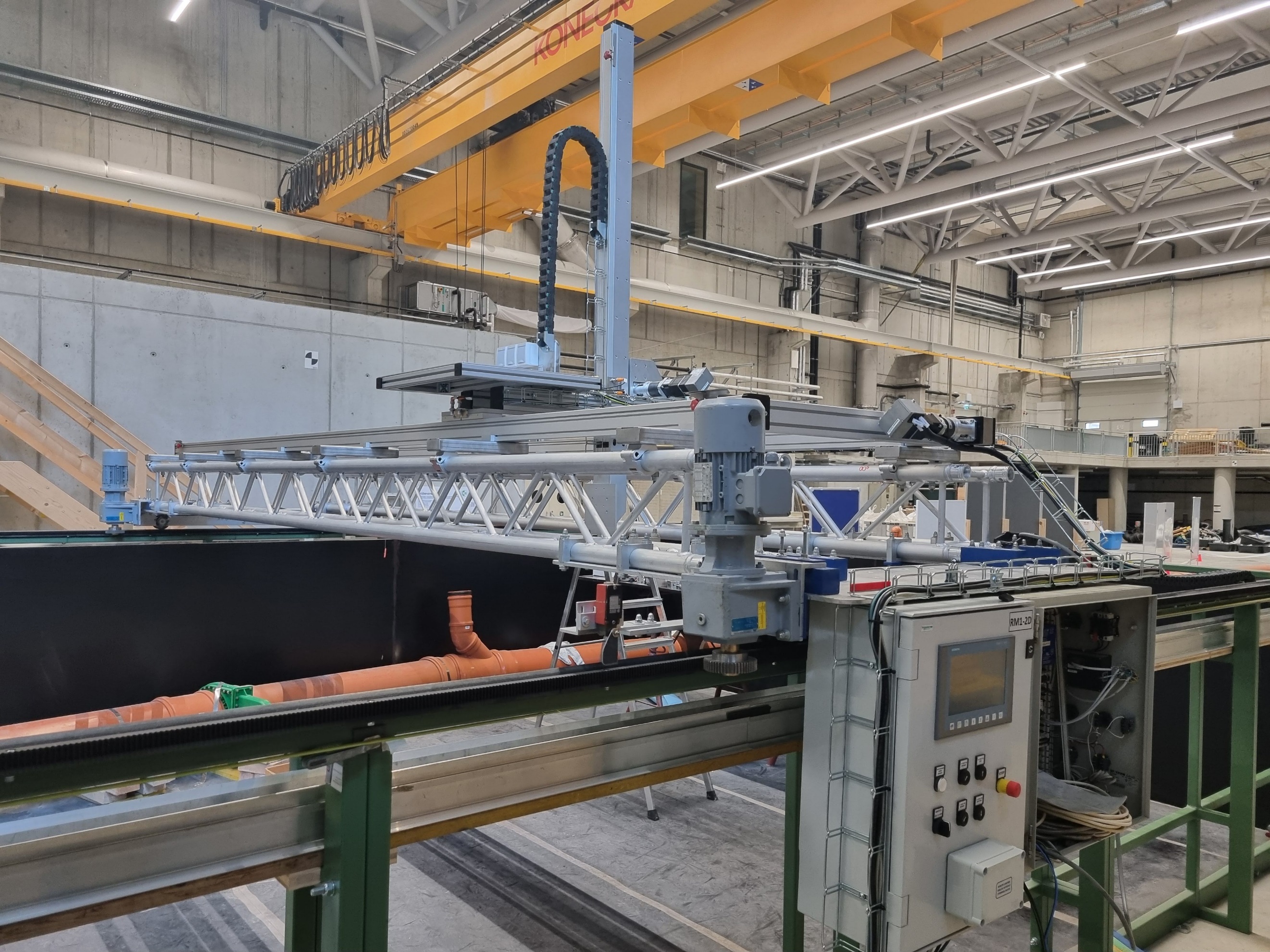
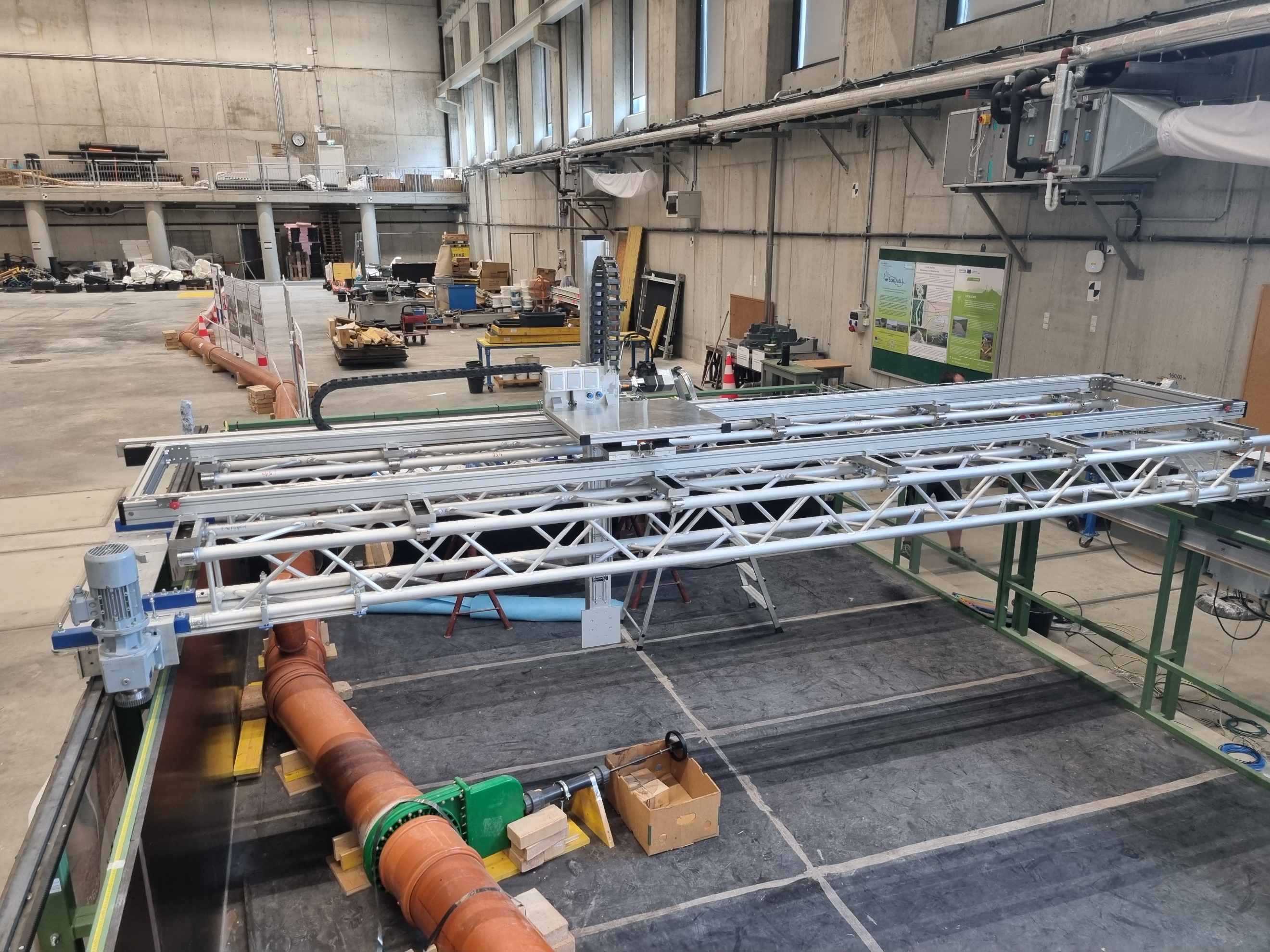
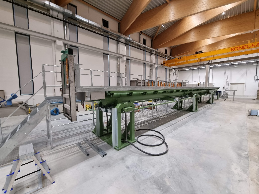
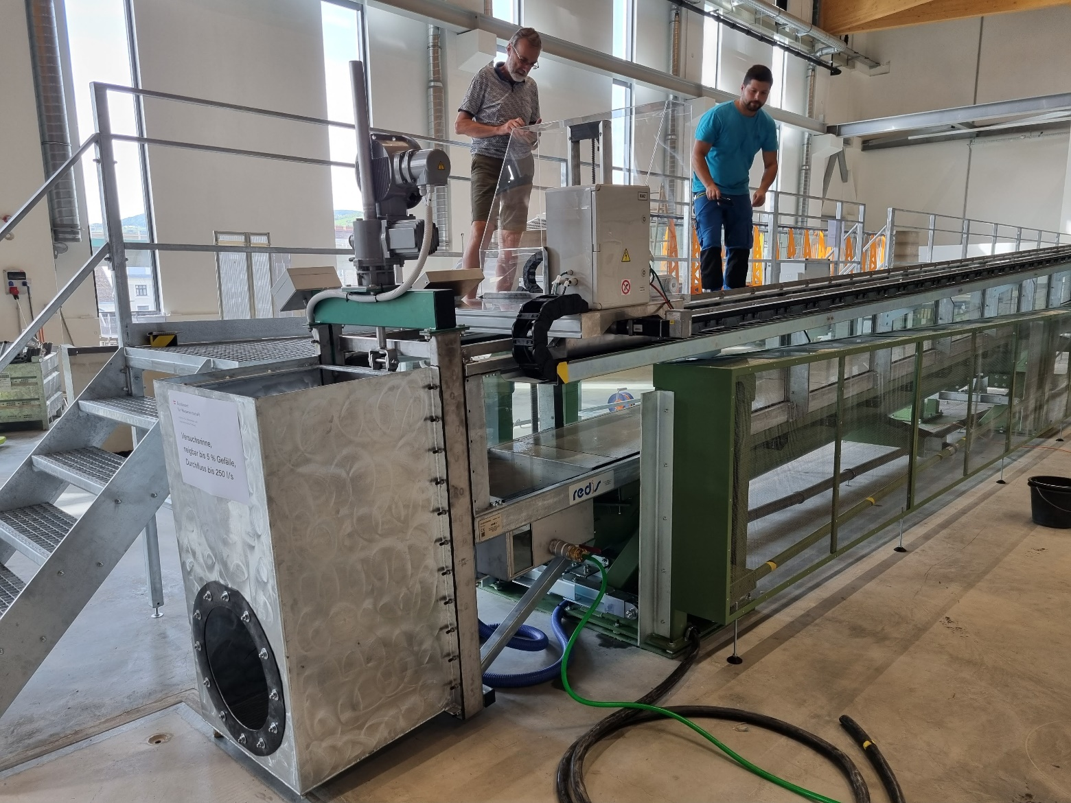
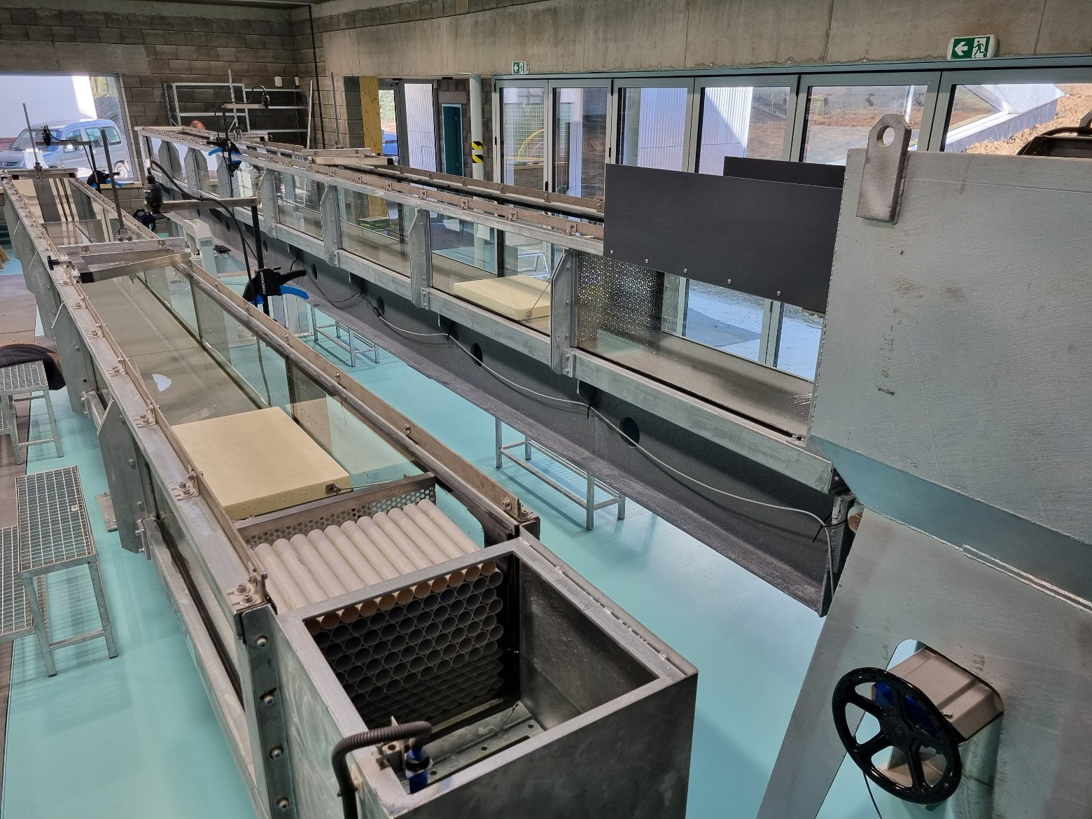
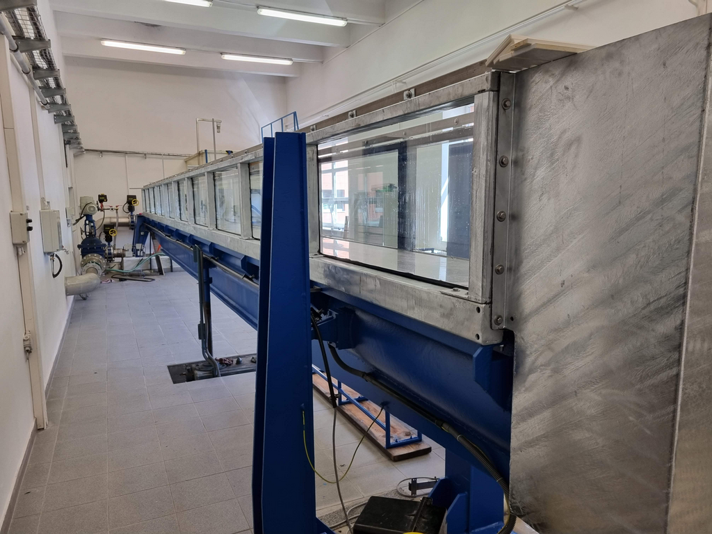
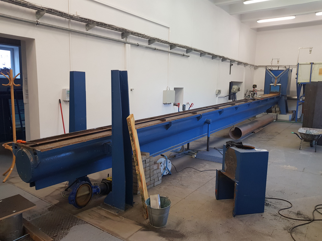
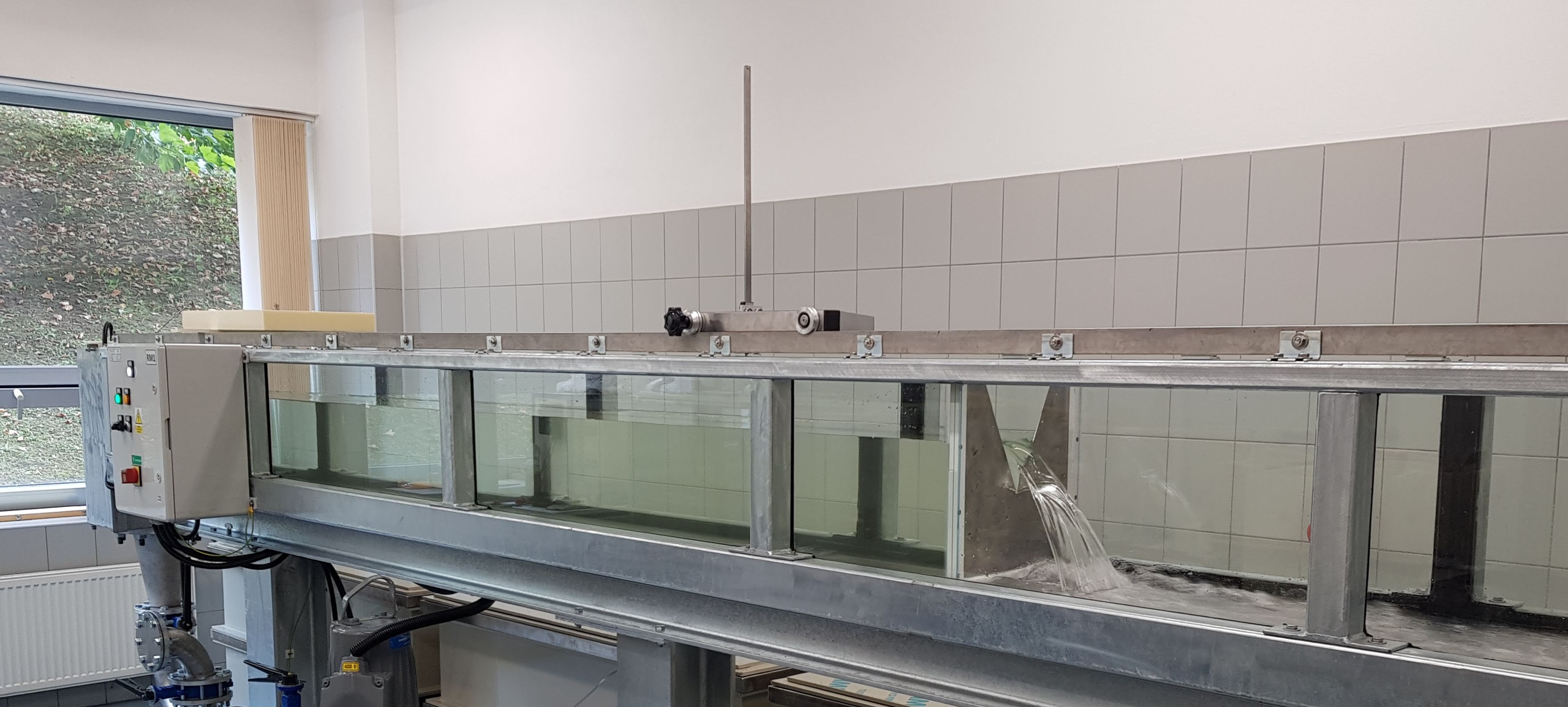
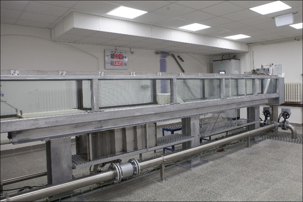
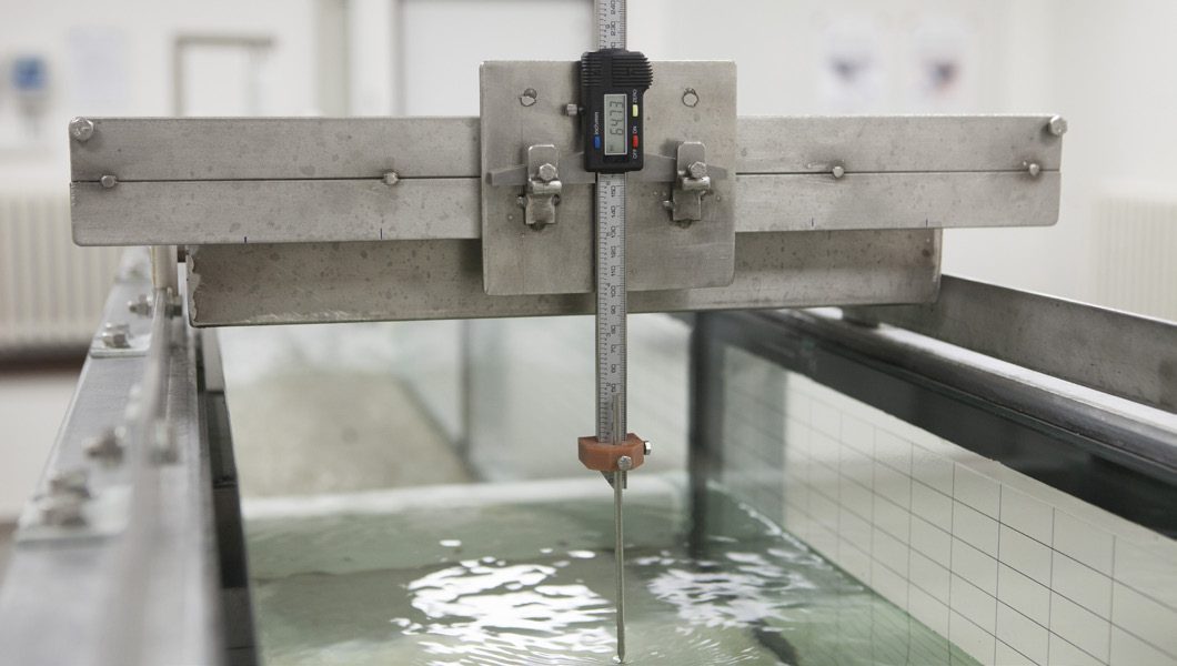
As part of the hydraulic circuit, a total of three measuring tracks were designed, of which the most important is a hydraulic measuring flume with a total length of 6.50 m. It is designed as a fixed flume, non-folding with glazed side walls, a stainless steel bottom and a width of 0.36 m. The whole structure of the measuring flume is galvanized. 
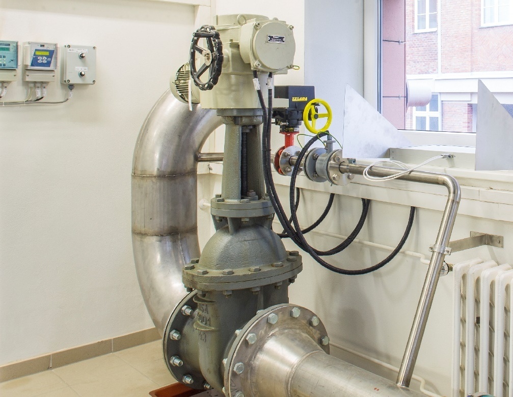
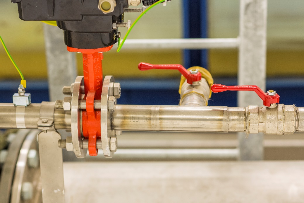
The second of the three tracks is a pressure operated measuring track which serves for simulation of the mechanical losses of energy by friction along the pipeline length and the local losses. The last of the three tracks is a spare track which will be later used for supplying standalone models. The hydraulic circuit delivery includes hydraulic models of structures. For the presentation of flow in the hydraulic measuring flume, 5 sharp-crested spillways, a streamline spillway and a dismountable culvert are designed. 
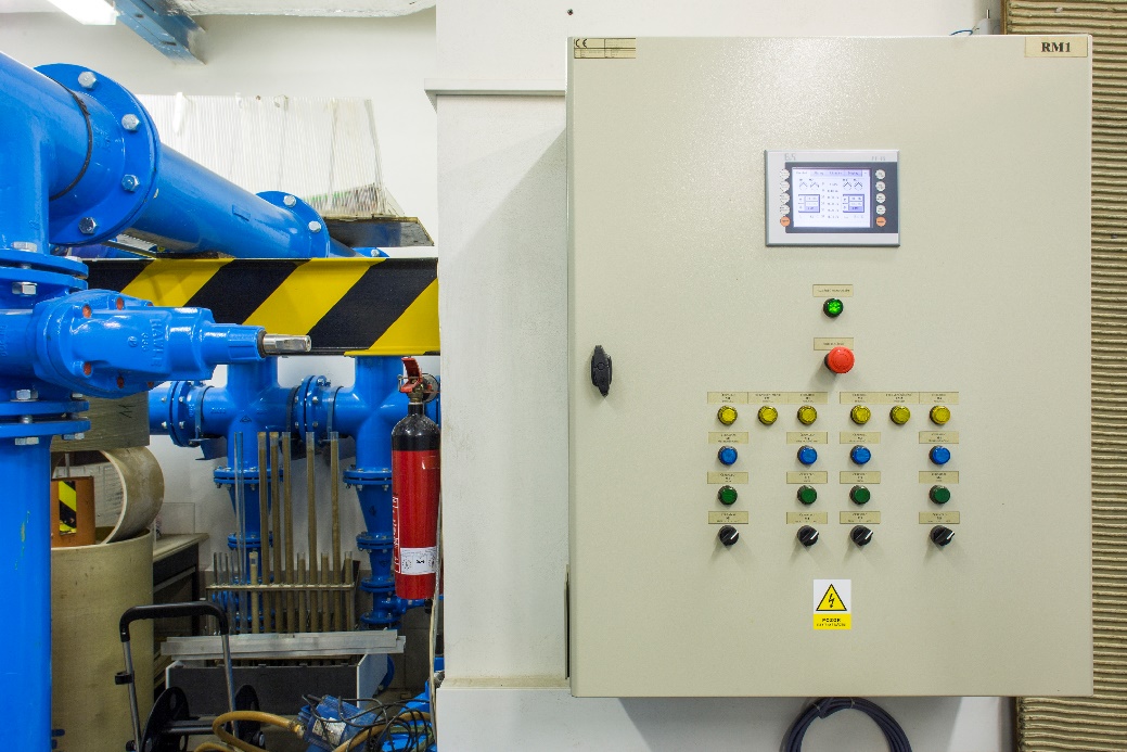
The electro-technological part of the laboratory is made up of a system of cable routes, measurement and control cables, a control and visualization system. The hydraulic circuit is operated via a 10” touch display which is a part of the electric switchboard.

2010


Adaptation of the Measuring Tracks of the Hydraulic Circuit of the Institute of Water Structures’ Laboratory for Low-Flow Measurements

To measure low flows in a range from 0.3 l/s to 7 l/s, two of the existing measuring tracks of the hydraulic circuit were provided with fully equipped bypass pipelines with magnetic-induction flow meters DN 40. The delivery included a change in the software of the hydraulic circuit control system and delivery of large LED display panels of instantaneous flow rates through the measuring tracks.

2009


Modernization of the Hydraulic Circuit of the Institute of Water Structures’ Laboratory at the Faculty of Civil Engineering, Brno University of Technology

The existing hydraulic circuit uses an underground storage tank with a capacity of 30 m3, from which the water is transported by a cast steel pipeline to a total of four measuring tracks. The pumping station is equipped with four Zenit centrifugal pumps of which two are “small” with a capacity of 2 x 12 l/s and two are “large” with a capacity of 2 x 95 l/s. The electro-technological part was innovated as part of the modernization of control in this hydraulic circuit. All electric elements are installed in a switchboard cabinet in which also two frequency converters and the control system are located. In this case, the control system is integrated in a 6” visualization touch panel from B&R, and its desktop can also be displayed on a distant computer

2008


Reconstruction of the Pumping Station of the Institute of Water Structures’ Laboratory at the Faculty of Civil Engineering, Brno University of Technology

The machine-technological and electro-technological parts were innovated as part of the reconstruction of the hydraulic circuit’s pumping station. The machine-technological part of the pumping station is made up of two Flygt submersible centrifugal pumps (installed into the original pump tank), stainless steel pipelines in dimensions from DN 150 to DN 300 with six flap gates and an induction flow meter. The routing of distribution pipelines along with the positions of flap gates are designed with respect to the possibility of simultaneous independent operation of multiple measuring tracks. From the technical point of view, the electro-technological part of the innovated pumping station can be divided to a system of electric power cable routes, measurement and control cables, and the control and visualization system alone. That is installed in two bays of a switchboard cabinet in which there are also the frequency converters of submersible pumps with accessories. The control system from B&R, which is a part of the 10” visualization touch panel, serves for complete control, monitoring and archiving of all non-electric operating quantities. Thanks to the PID flow-rate control it is possible to simulate a slowly changing flow rate in the hydraulic circuit.

2007


Adaptation of the Measuring Track of the Hydraulic Circuit of the Institute of Water Structures’ Laboratory for Low-Flow Measurements

To measure low flow rates in a range from 0.1 l/s to 3 l/s, one of the existing measuring tracks of the hydraulic circuit was provided with a fully equipped bypass pipeline with a magnetic- induction flow meter DN 32. The delivery included a change in the software of the hydraulic circuit control system.

2003


Delivery of Measurement and Automation for the Newly Built Hydraulic Laboratory of the Institute of Water Structures at the Faculty of Civil Engineering, Brno University of Technology

In 2003, a new laboratory of the Institute of Water Structures was built. As well as other hydraulic circuits, it is based on the existence of an underground storage tank with a capacity of up to 60 m3 of water. The laboratory is equipped with four Flygt submersible centrifugal pumps. Two small pumps with a capacity of 2 x 15 l/s and two large ones 2 x 100 l/s. Conceptually, the hydraulic circuit can be operated in two modes – in gravity or pressure operation. The total flow capacity of the circuit is 230 l/s. The main water distribution pipelines are of stainless steel type in dimensions DN 200 to DN 350. The pipeline is equipped with a total of 12 flap gates and 5 adjustable slide valves. Induction flow meters are used for flow measuring; in the gravity mode the flow rate is determined by a Thomson measuring weir. Within the project, complete electro-technological equipment was supplied, comprised of electric power cable lines, measurement and control cables, and a switchboard cabinet with a total of four bays. Apart from frequency converters, the switchboard contains a Simatic S7-300 control system from Siemens, which is connected with the control and visualization PC, and its desktop can also be displayed on a distant computer. The laboratory can also be controlled from two parameterization panels. The system registers a total of approximately 70 data of electro-technological quantities. The regulation of flow rates to individual measuring tracks is controlled by a PID controller in automatic mode. Thanks to the PID control, it is possible to simulate a slowly changing flow rate in the hydraulic circuit. In pressure mode, the system allows supplying up to three measuring tracks simultaneously.